In this lesson we’re going to let a LED-Matrix showing a Smiley.
For that do we need:
- 1 Arduino
- 1 Breadboard
- 1 LED-Matrix 8×8 (e.g. SH1388ASR with common cathode or 1588BS with common anode)
- 8 220Ω Resistors
- 16 Jumper
Let’s start with the program code.
We have to tell the Arduino, on which pins the rows and columns have been connected. To make it in a simple way, we define an array and a for-loop, which defines the Arduino pins.
An array with content will be defined like this:
var_type var_name[size] = {val_0, val_1, val_2, val_n};
e.g.: int rows[8] = {10,18,9,13,2,8,3,6};
The const before the variable type defines a constant variable. It helps the compiler to to compile the sketch in a better way.
You use the for-loop like this:
for(init counter; test counter; increment OR decrease counter)
{
//program code
}
For example (do things eight times, from zero to eight):
for(int i = 0; i < 8; i++)
{
//program code
}
That for-loop in a sentence means:
For an int i with 0, while i < 8, increase i plus one, do the program code.
Now we have to define a two dimensional array for our smiley (1 = on, 0 = off). It’s the same like a normal array, just with to indexes:
var_type var_name[size_row] [size_column] = {
{val_0, val_1, val_2, val_n}, /*row 0*/
{val_0, val_1, val_2, val_n}, /*row 1*/
{…}
};
In the loop() method we have two for-loops in each other, to jump from row to row and from column to column.
//Pins, connected to the rows (220 Ohm resisor)
const int rows[8] = {10,18,9,13,2,8,3,6};
// Pins, connected to the columns
const int columns[8] = {19,4,5,11,7,12,17,16};

int smiley[8][8] = {
{0,1,1,0,0,1,1,0},
{0,1,1,0,0,1,1,0},
{0,0,0,0,0,0,0,0},
{0,0,0,1,1,0,0,0},
{0,0,0,1,1,0,0,0},
{0,1,0,0,0,0,1,0},
{0,0,1,0,0,1,0,0},
{0,0,0,1,1,0,0,0}};

void setup()
{
  Serial.begin(9600);
  //set the pins to output
  for (int pin = 0; pin < 8; pin++)
  {
    pinMode(rows[pin], OUTPUT);
    pinMode(columns[pin], OUTPUT);
    //all LEDs off
    digitalWrite(rows[pin], LOW);
    digitalWrite(columns[pin], LOW);
  }

}

void loop()
{
  for (int row = 0; row < 8; row++)
  {
    for (int column = 0; column < 8; column++)
    {
        digitalWrite(rows[row],HIGH);
        digitalWrite(columns[column], !(smiley[row][column]));
        digitalWrite(rows[row],LOW);
        digitalWrite(columns[column],HIGH);
    }
  }
}
To see, what your code is doing, you have to build your circuit. Do it according to the following scheme:
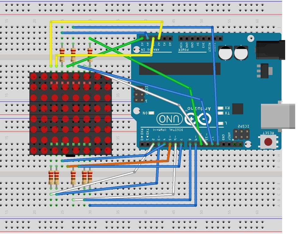
Source: http://mikrocontrollerkochbuch.de/index.php?title=Matrix-Modul_mit_8_x_8_LEDs_Version_1
| ⇐ Lesson #4 | Lesson #6 ⇒ |